Voids under your thermal pads?
Here's how to reduce solder voids.
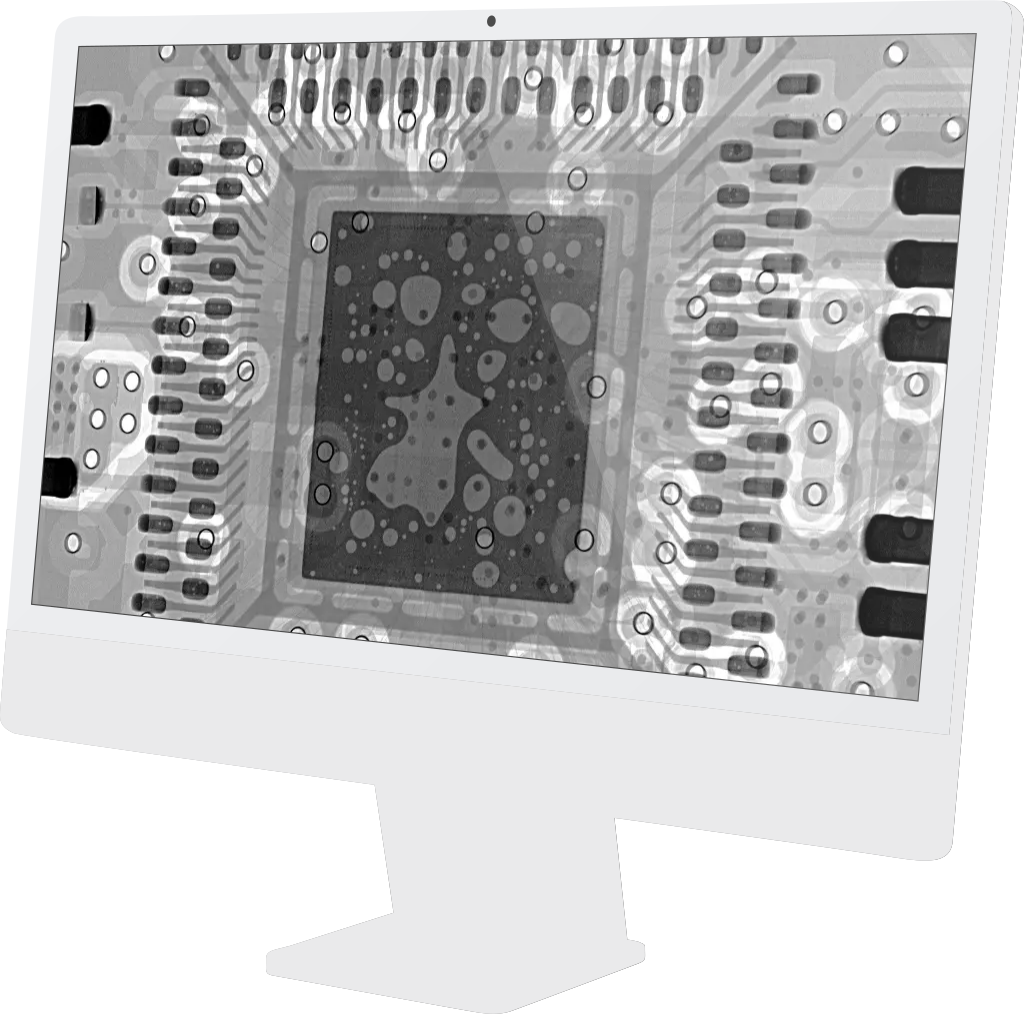
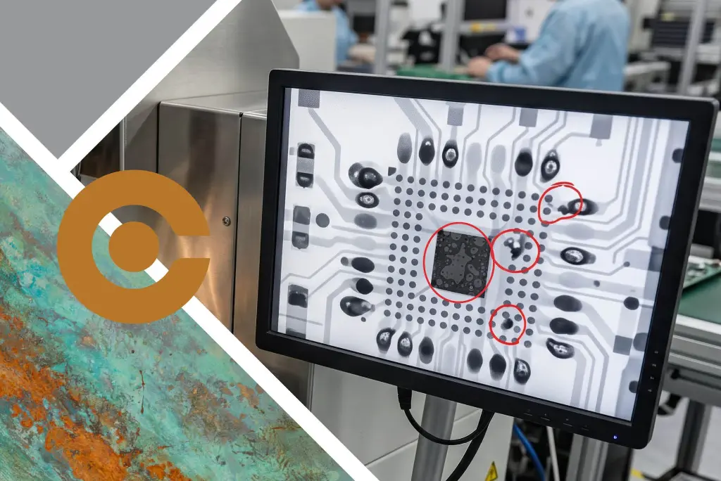
Your customer won't see voids - only the effects later.
However your X-ray sees it now.
The small bubbles trapped under a QFN, a power module or an LED. They look harmless. But every void is a spot where heat can't escape and where the joint is weaker than it should be.
The good news? You can reduce solder voids, often by a lot. Some fixes cost next to nothing. Others call for a different kind of reflow process.
Here we walk you through both, so you can decide what makes sense for your production.
Why solder voids happen and how to reduce them

What causes solder voids?
Voids form when gas gets trapped in the joint while the solder is molten. Most of that gas comes from the flux in the solder paste, with oxidation on paste, pads or terminals adding to it. If the solder solidifies before the gas escapes, the void stays.
Several factors play a part:
- solder paste formulation and flux type
- pad size and design
- stencil design
- your thermal profile
Large, flat thermal pads are the usual suspects. Gas has a long way to travel to escape from under a big component, and often it doesn't make it.
Why voids cost you more than you think
A thermal pad is there to move heat away from the component. Voids block that path, so the component runs hotter. Over time, that can shorten its life and weaken the joint as the product heats up and cools down, again and again.
For EMS companies, voids mean boards held back at X-ray inspection, rework and awkward conversations with customers.
For OEMs, the risk shows up later, in the field. Either way, the cheapest void is the one that never forms.
Five ways to reduce solder voids on your current line
Before you invest in new equipment, check the basics. These steps often make a noticeable difference:
- Review your solder paste. Some pastes are formulated for low voiding. Ask your supplier and test against your current paste.
- Split the stencil aperture. Use a windowpane pattern instead of one large opening on the thermal pad. The gaps give gas an escape route.
- Look at pad and via design. Open vias in a thermal pad can pull solder away and trap gas. Involve your PCB designer early.
- Fine-tune the profile. A well-balanced soak gives flux volatiles time to escape before the solder melts.
- Use nitrogen. A nitrogen atmosphere reduces oxidation, one of the sources of voids. Our reflow ovens come in air and nitrogen versions.
Measure on X-ray before and after each change, so you know what actually better the issue.
When vacuum reflow is the next step
Sometimes the basics aren't enough. Maybe your customer specifies a maximum void level, or your product has large thermal pads where heat transfer is critical.
Power electronics, LED modules and automotive electronics are typical examples.
That's where vacuum reflow comes in. Instead of hoping the gas finds its own way out, you pull it out.
How vacuum reflow removes voids
In a vacuum reflow oven, the PCB enters a sealed chamber while the solder is still molten. The pressure drops, the trapped gas expands and escapes from the joint. The chamber is then refilled, and the board moves on to cooling.
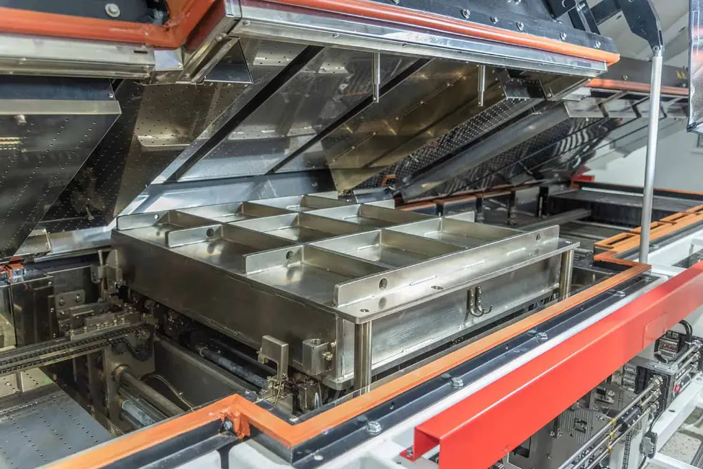
Here's how it works in the BTU Aurora 125 vacuum reflow oven:
- Voiding below 5%
BTU's vacuum process is designed to bring voids under 5% (process dependent). - Peak temperature under vacuum
Without heat inside the chamber, the peak has to happen before the board goes in, and the solder must stay molten for longer. Radiant heaters in the chamber take care of the final heating, so time above liquidus stays close to what you know from standard reflow. - Components stay put
A soft-start vacuum lowers the pressure gradually, so small parts don't move.
- A short vacuum step
Pump-down takes 15 – 25 seconds, hold time is 0–60 seconds and re-pressurisation is under 8 seconds.
What it means for your SMT line
Vacuum adds a step for every board, but the design keeps it efficient. The 620 x 711 mm vacuum chamber has room for large-format PCBs. Choose the dual-lane option, and you can run two products in parallel. Three independent conveyors move boards through heating, vacuum and cooling, so each section runs on its own.

The oven is built on the BTU Aurora platform, so you get the latest Aurora features as well. With a total length of 7.255 mm, it's worth planning floor space early.
Is vacuum reflow right for you?
Vacuum reflow is worth a closer look if you:
- still see voids on X-ray after optimising paste, stencil and profile
- build assemblies with large thermal pads, power modules or LEDs
- have customers with strict void requirements
- want to keep critical assemblies in-house instead of outsourcing them
If none of these apply, a well-tuned nitrogen reflow process may be all you need.


Let's look at your voids together
Every line is different, and so is every void problem. Tell us what you see on X-ray, what you build and what your customers require.
Our SMT specialists will help you work out whether better process settings will do the job, or whether vacuum reflow is the right next step.
See the BTU Aurora 125 vacuum reflow oven or contact our experts.